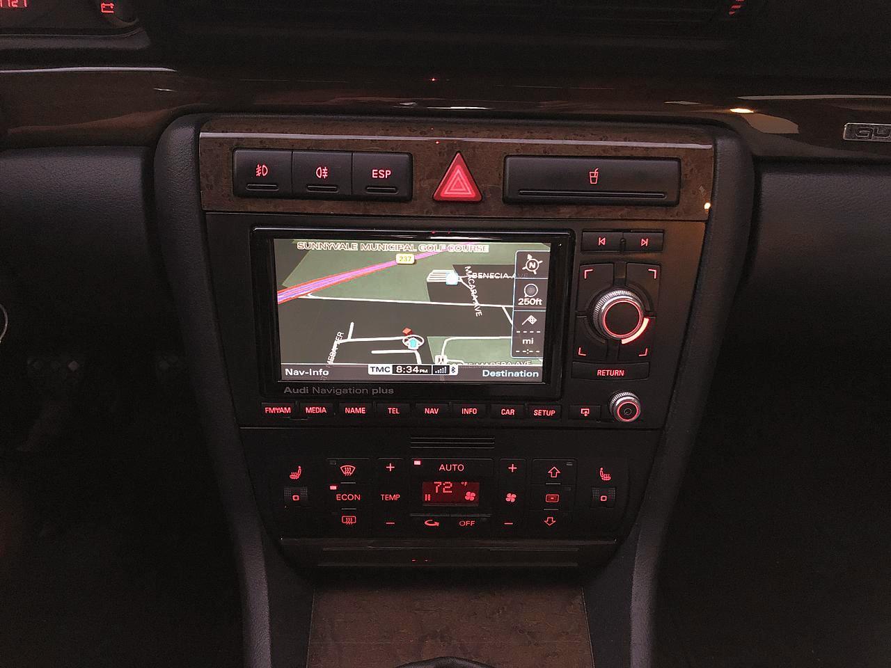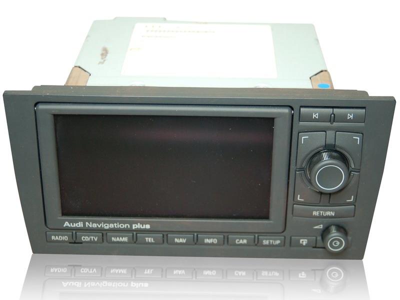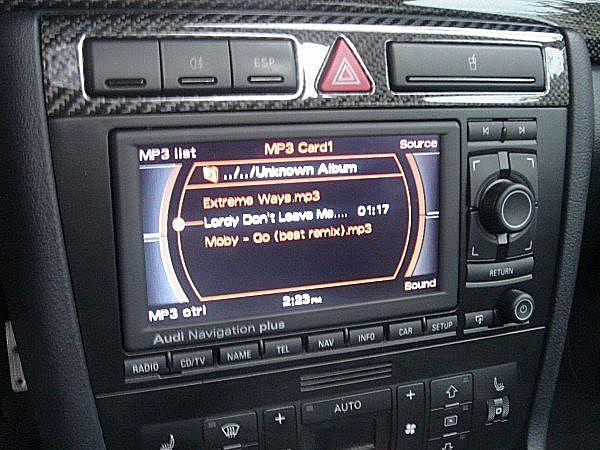
Click any picture on this page to enlarge IntroductionThe "Audi Navigation Plus" RNS-E (Radio Navigation System type E) is an advanced console mounted unit serving as a central interface to FM/AM radio, single CD and SD card (2 slots) music playback, DVD-based GPS navigation with voice guidance and name directory. It also optionally controls an external CD changer, Bluetooth hands-free phone module, satellite radio tuner, rear view camera and other devices. Multi-function steering wheel (MFSW) is also supported if equipped (but I don't think any B5 Audis have it). The RNS-E mk2, introduced in 2010, adds some enhancements (see below).The RNS-E is found as optional or standard equipment on some Audi models from approximately 2007 through 2012, as well as on Lamborghini and other Volkswagen AG family brands with different labeling. A display screen occupies much of the front panel, with MMI-style (Multimedia interface) controls featuring a large push/turn dial, four quadrant pushbuttons and a Return button providing primary means of navigating the menus and features. Individual pushbuttons access the major subsystems, forward and backward selection, and a smaller knob controls the volume and power on/off. Pressing a special button causes the motorized screen to fold out, revealing a CD/DVD drive slot and two SD card slots. The circa 1995-2002 Audi B5 A4/S4/RS4 (type 8D) platform never came fitted with the RNS-E from the factory, as the platform pre-dates the RNS-E. However many DIY enthusiasts have retrofitted the RNS-E, replacing the stock radio head unit. Doing so adds many new capabilities that were not previously available on this platform. The reasons for retrofitting RNS-E rather than installing an aftermarket unit are as follows:
I have done this retrofit on my own B5 Audi S4, first with an RNS-E mk1, and then upgraded to a mk2. I had also retrofitted an RNS-E mk2 into my B6 Audi A4. I am sharing the information I learned from the process, in the hopes that the information would be helpful to others who want to do likewise. The retrofit is not a direct drop-in for several reasons, which will be covered in the sections below. * While earlier Audi radios display information in the cluster DIS, they used a proprietary communication scheme rather than the CAN bus (see below). Which cars are candidates for the retrofit
Since this article is about retrofitting the RNS-E into an Audi B5 platform, we limit the discussion to cars of this platform only. However, not all B5s are good candidates for such a retrofit. Unlike the original radio, the RNS-E makes heavy use of the infotainment CAN bus (Controller Area Network) for communication with the instrument cluster and other subsystems. The B5 platform did not have such a CAN bus until around model year 2000. Thus, only cars from that time and later, until the end of B5 production, are good for RNS-E retrofits. B5 cars with the needed CAN bus are identified by a digital clock in the instrument cluster rather than an analog one. Below are the instrument clusters found on B5 cars. Only cars with the bottom cluster (#3) has the needed CAN bus. 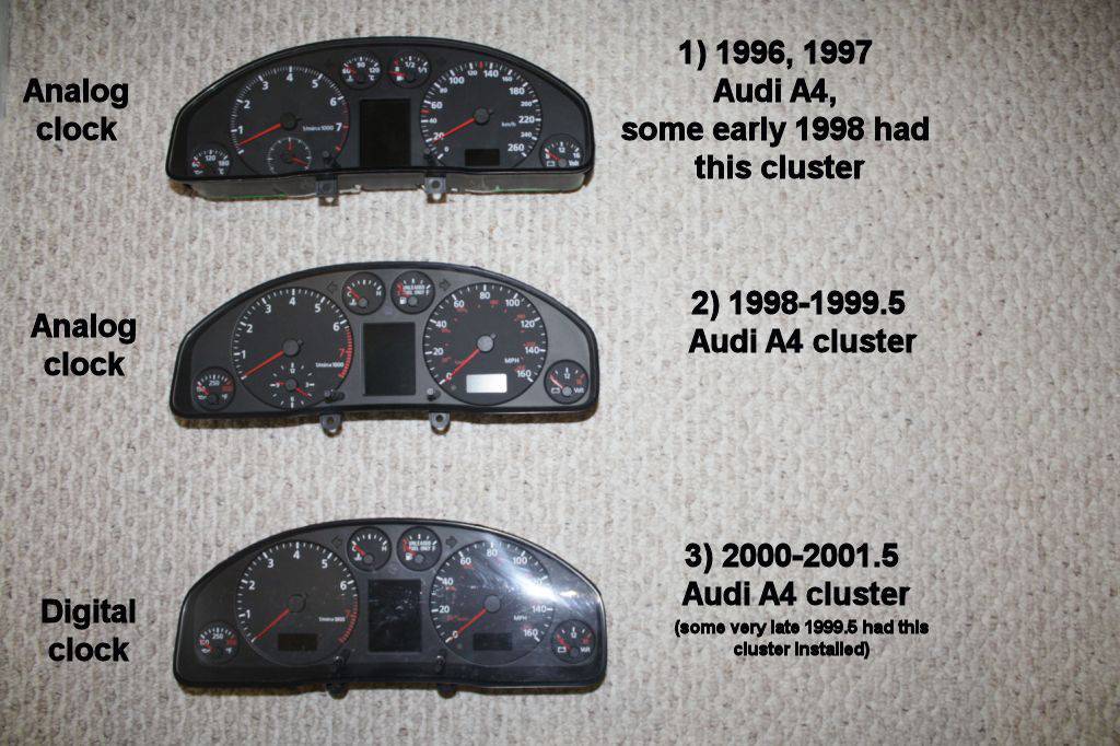 Audi B5 instrument cluster versions (Credit: from this Audizine thread) Without the CAN bus, the RNS-E's button illumination will not light up when you turn on your parking lights or headlights. The unit will not shut off or turn on with the ignition key, and the navigation screen will not change between day and night mode based on whether your lights are turned on. Moreover, the radio and navigation supplemental info will not be shown in the instrument cluster's DIS, and the cluster's clock will not be sync'ed on the RNS-E screen. These are only some examples of the loss of functionality sans CAN bus. There are a few people who installed the RNS-E in non-CAN cars using a CAN emulator, but many functions will still be missing and the results are not satisfactory. 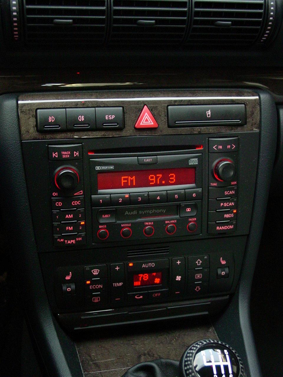 The original Symphony radio For North American markets, all post-2000 B5 A4/S4 models came with the Audi Symphony radio, which is a double-DIN unit. The RNS-E is also double-DIN, thus no modification to the car's center console is necessary for the RNS-E. In Europe and other world markets, single-DIN radios may have been installed as standard equipment on some cars. If you have such a car, then you need to perform a swap of the center console to the double-DIN version. This may involve the replacement of the appropriate climate control head too, and is beyond the scope of this document. Which RNS-E to use
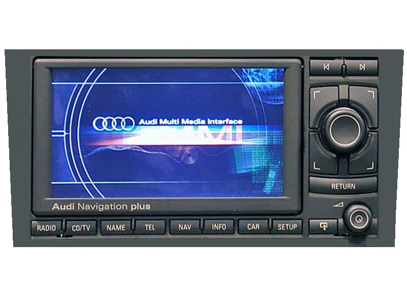
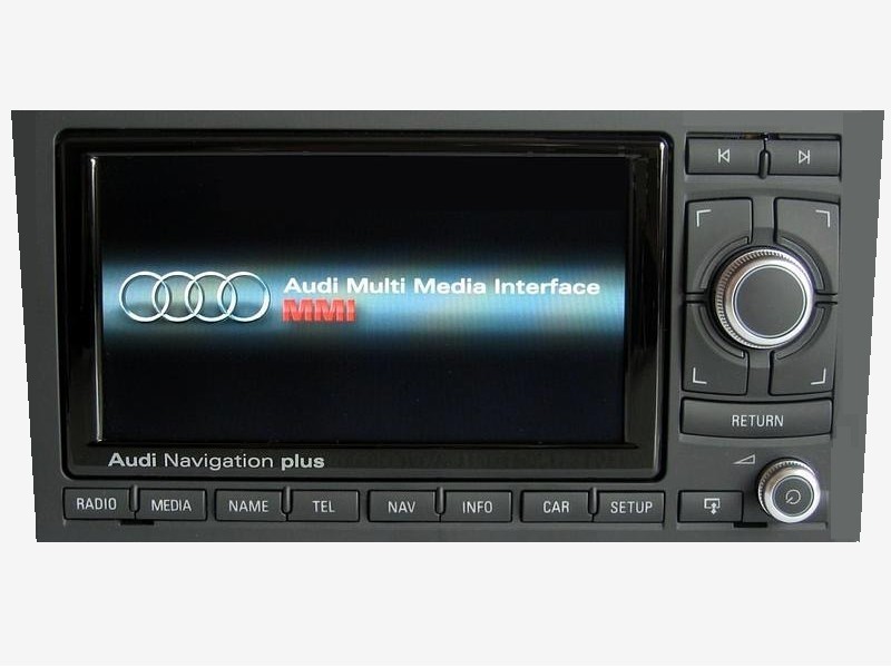
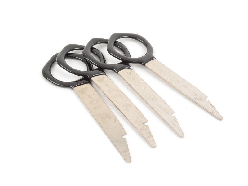
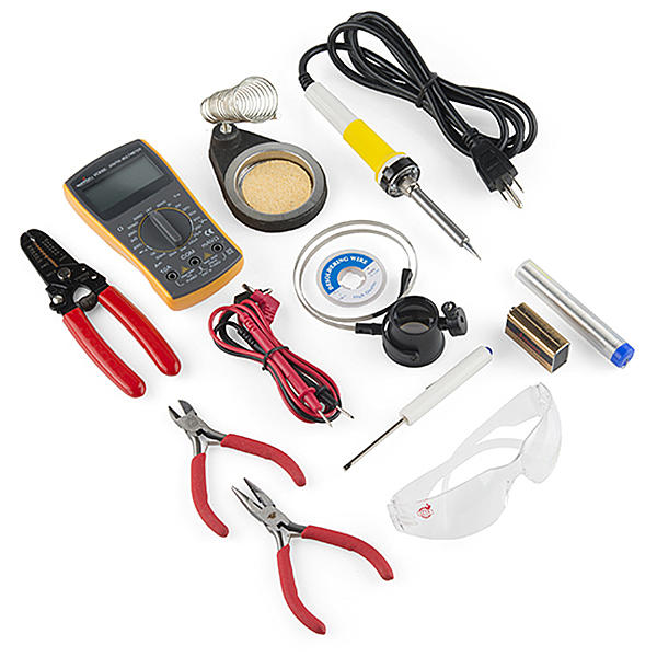
There are different part numbers for various versions of the RNS-E. They take the form: xx0 035 192 ywhere xx is the platform code and y is a revision letter. For example, 8E0 035 192 J refers to an RNS-E for the A4/S4 type 8E B7 sedan and Avant platform), with revision J. The internal electronics is the same regardless of the platform, but the front panel is shaped to fit the specific platform. Note that there are different revisions for North America models than those for the European market. If you purchase an RNS-E, be sure to get one appropriate for your region. Depending on the platform and revision, the RNS-E may have black knobs for the MMI and volume controls, or ones with aluminum/chrome accents. Some C5 A6 versions also have a gray panel rather than black. Starting around 2010, a new RNS-E "mk2" was introduced with similar part number scheme, except the last three digits of the part number is 193: xx0 035 193 yIn addition to the part number, the mk2 unit is identifiable by the labeling of the second button on the lower left as "MEDIA" rather than "CD/SD" (North American) or "CD/TV" (Europe). Either mk1 or mk2 RNS-E could be used for the retrofit. The mk2 offers several improvements such as a better display (800x480 resolution, compared to mk1's 400x240), faster processor, support for SDHC cards up to 32GB (compared to mk1's SD cards up to 4GB maximum), and built-in TMC (Traffic Message Channel), The mk2 also have improved screen visuals, such as color gradient shading on text entry fields as opposed to mk1's solid colors, better navigation map renderings, some rearranged menus, etc. etc. Note that the chrome-accented knobs and glossy black screen bezel shown on the RNS-E mk2 above may also be found on some mk1 units, so they should not considered a visual differentiation between the two. The mk2 unit is rarer and costlier, and have additional issues being integrated on the B5 platform that need to be addressed, these will be covered in the sections below. There is a version of RNS-E for the Audi R8 with its MMI and volume controls at the bottom (423 035 192 y). This version is not suitable for use to retrofit into a B5 Audi. Center console fitment issueSince Audi never equipped the B5 platform with an RNS-E from the factory, there is no 8D version of the RNS-E. This means that the front panel on any version of the RNS-E will not fit the opening in the B5 center console opening perfectly. The closest one is the one for the C5 A6 (type 4B platform), it will physically fit in the B5 console, but there will be gaps on the two sides.For the best fit and appearance, people have done custom work to make it fit the B5 center console perfectly by modifying the RNS-E panel. For this, virtually any version of RNS-E could be used. Read this Audizine forum thread about making/modifying a front panel for the B5. There are also individuals who custom make front panels for a fee. If you need a referral, contact me. Parts and tools needed for a basic retrofitThe following are the essentials necessary for retrofitting an RNS-E into a B5.
InstallationWhen your front panel has been modified to fit the center console properly, and you have all the parts mentioned above, then you are ready to install the RNS-E. These are the basic steps of retrofitting the RNS-E into a B5 car. Make sure to read through the rest of this article in case you need to make additional changes to the quadlock adapter before installation.If your car is equipped with the CD-based BNS navigation system (with trunk-mounted module including the CD reader), you must remove it before installing the RNS-E, as the BNS functionality is being replaced by the RNS-E. The BNS controls next to the parking brake lever will no longer be used. Before you begin, here are some essential information about Audi/VW electrical wiring that you should know:
Unlocking RNS-E with the 4-digit security PIN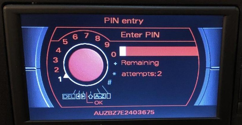
For some reason, on the B5 platform, when the RNS-E needs unlocking (after the power has been disconnected), it becomes reluctant to unlock even if you enter the correct PIN. It does not consider the PIN to be incorrect, and the remaining retry attempt count stays the same, but it just doesn't unlock. What I found to work, is to turn on the ignition, attempt to unlock by entering the PIN (it doesn't unlock), but then turn off the ignition and wait about 10 minutes. Next, turn on the ignition and start the car. Now try to unlock again. It will likely work at this point. If not, repeat the above cycle. Once unlocked, it will remain so until the power is disconnected again. RFSL line for reverse gearThe original radio wiring is missing the RFSL signal, which tells the RNS-E when reverse gear is engaged. The quadlock adapter pin C2 for RFSL is probably not wired to anything. The navigation system uses this signal to "know" that you're in reverse gear, and that any movement is in the reverse direction. It can improve navigation accuracy, such as when the car has just been started, but the RNS-E has not yet acquired a sufficient number of satellites to establish its location, or when it's in an underground garage with no GPS reception. In these circumstances it relies on its last known location, plus the current travel direction and speed to continue to locate itself.It is optional to connect the RFSL line for navigation purposes, with the caveat that it may sometimes lose locational accuracy. But having acquired enough satellites the RNS-E should be able to restore its locational accuracy. If you also plan to install a rear view camera, then it is required to connect the RFSL line. This signal will trigger the RNS-E to switch the screen to the camera view when you engage reverse gear. A convenient location to tap the RFSL signal is the back-up light circuit. There is a blue/red wire in the connectors station (inside the cover below the left side A-pillar) that you could splice into, located in a light brown 10-pin connector, shown in the photo below. The multimeter probe points to the wire. To access this connector station, remove the cover over this area (remove 2 screws - the top one near the hood release lever, the lower one behind a small cover that you pry open to reveal, and peel back the door seal a bit). 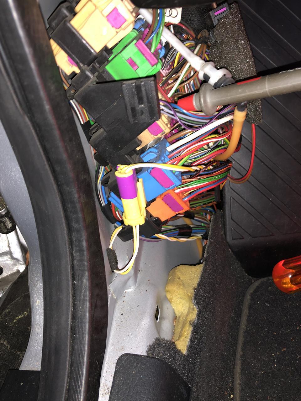
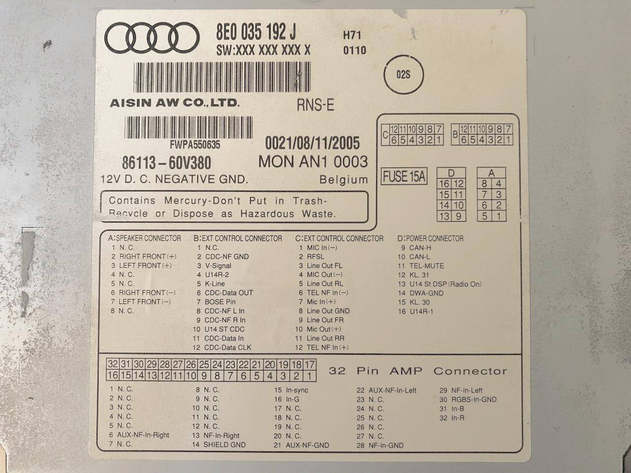
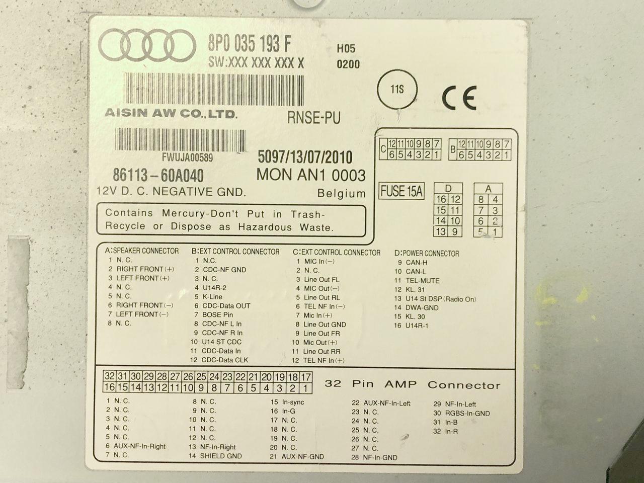
Use a multimeter to test the voltage at this location to make sure it's normally 0V, and only goes to 12V when the ignition is on and shifted into reverse. This ensures that you have found the correct wire. To add the RFSL line to the RNS-E, use Audi/VW repair wire part number 000 979 009, which comes with the correct female crimp pin on the end to push into location C2 on the quadlock adapter. The other end of this wire also has a female crimp pin but you won't need it, so just cut it off and splice it into a longer 20 AWG wire to extend it to the connectors station below the A-pillar, and splice it into the aforementioned red/blue wire. I used a 1-circuit Molex .062 connector (see below) instead of a splice, to allow it to be unplugged. Insulate all splices with heat-shrink tubing, and make sure the added wire won't get tangled with the steering column shaft or foot pedals. V-Signal and RFSL lines on some RNS-E mk2 unitsOn some later production RNS-E mk2 units, the V-Signal (vehicle speed) and RFSL (reverse gear active) lines are no longer supported. The hardware that handles those inputs within the unit has actually been deleted. Instead, the unit expects CAN bus messages from the instrument cluster for this information.The reason for this change is apparently because the chip used for this has been discontinued, and the RNS-E mk2 was never installed on any Audi model that use those signals. You can identify such a unit by examining the label on the top cover. If the B3 and C2 pins are labeled "N.C.", then you have one of these units. The following photos shows the label on an older RNS-E with support for these lines, and a newer mk2 unit that doesn't.
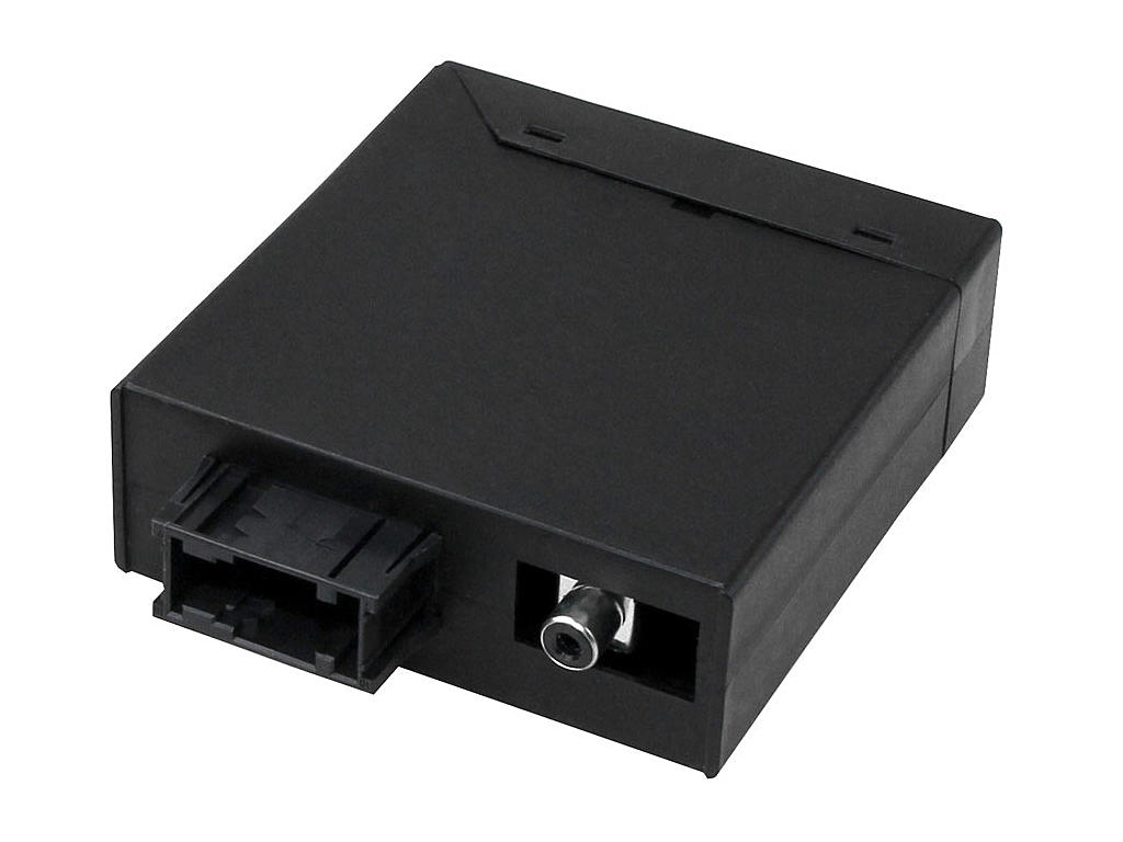
Unfortunately, the B5 instrument cluster does not send V-Signal and RFSL status over the CAN bus. Without V-Signal, navigation will not function properly. RFSL is needed for location accuracy under certain circumstances, and required if a rear view camera is to be installed. The solution is a "translator" module that turns V-Signal and RFSL hardware signals from the car into CAN bus messages that these later RNS-E mk2 units expect. Such a module, the Arduino-based "RFSL/V-Signal Injector" is available for purchase from Stuart M. at RNS-E Firmware Updates, or you could build your own. The open source sketch (firmware) is available from the site. 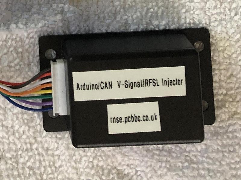
To use the RFSL/V-Signal Injector module, you will need to run a wire from the lower A-pillar connectors station as described above. The module supplied from Stuart M. has 8 wires, 6 of which must be spliced into your quadlock adapter. The wires are labeled and should be obvious where to connect each one. The wire labeled "RFSL" should be connected to the wire you pulled from the lower A-pillar connectors station (use a connector that you could unplug). The "PDC LED" wire is unused, and should be insulated and tucked away. Once the module is connected, you can verify that the RNS-E is receiving the proper V-Signal and RFSL status by going into Engineering mode. Select "NAV" and then "Sensors", and look at the reverse gear status (REV) while putting the car into reverse gear, and the speed information (SPD) while driving the car. RNS-E mk2 and A6 supportAs mentioned previously, you must code the RNS-E for Audi A6 (C5) for proper functionality in a B5 Audi. The latest official Audi RNS-E mk2 firmware had dropped support for the A6 because none of the mk2 units were installed on that platform. In 2020, Stuart M. at RNS-E Firmware Updates developed and released new firmware that offers (amongst many other features) a solution to this problem. It re-introduced A6 support on the RNS-E mk2.Clock sync problemThe RNS-E displays the current time at the bottom of the screen. The source of the clock data is from the instrument cluster, sent over the CAN bus. Unfortunately, the clock data sent from B5 clusters is in the wrong format. The cluster data is in binary whereas the RNS-E expects it in BCD. The result is an incorrect time being displayed. It also affects the ETA information shown when guided navigation is in effect.This problem was discussed and understood in an audiforum.us thread, and member Bjarne developed a CANGate module that can be installed on the CAN bus between the instrument cluster and the RNS-E to act as a format translator. The Bjarne CANGate solved this problem, and he sold these units until around 2010. He stopped making them and have disappeared from the forums, the CANGate modules are now very hard to find. This problem can now be solved by updating the RNS-E firmware to the one from Stuart M. at RNS-E Firmware Updates. It automatically detects the clock data format discrepancy and corrects it. This firmware will also be necessary if you are using certain RNS-E mk2 units, or if you intend to install a rear view camera. CD changer or Phatnoise Phatbox
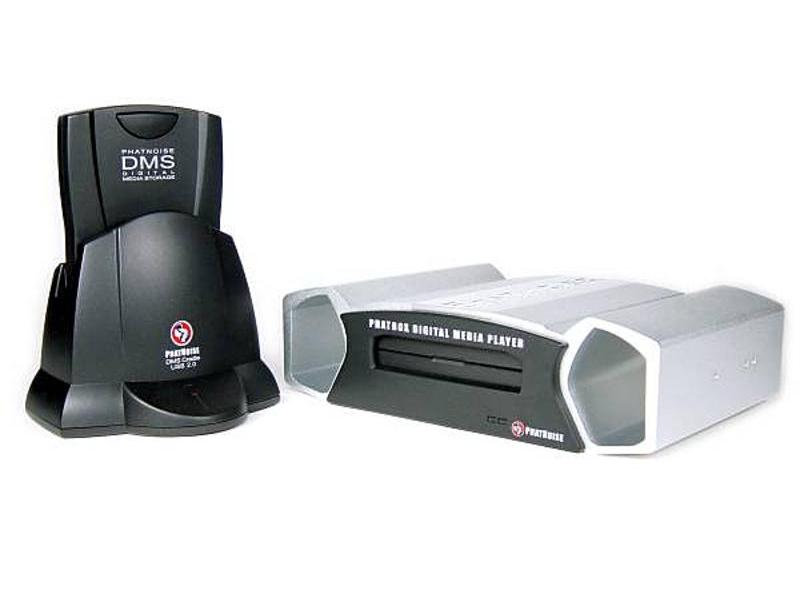
The Phatnoise Phatbox digital media player (Audi/VW version) can be installed in place of the CD changer via an adapter cable into the 13-pin CD changer round connector. Again, no modification is needed, and the Phatbox should be configured to operate with "Radio type T" by selecting CD number 6 on the RNS-E and going through the voice-guided prompts. I "hacked" my Phatbox to support larger disk drives in the DMS cartridge. This is described at the Phathack forum. I initially used a 320GB IDE 2.5" laptop HDD, but have since switched to a 500GB mSATA SSD with an 2.5" disk form factor mSATA-IDE adapter. Bluetooth hands-free phone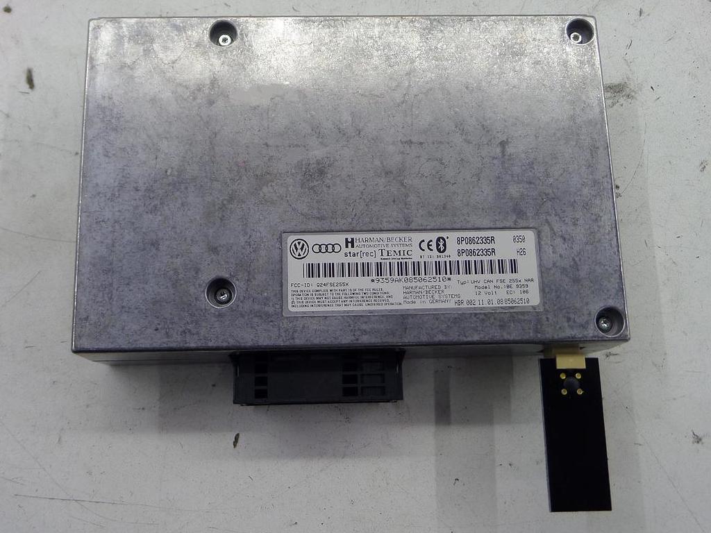
The Audi B5 platform comes pre-wired from the factory for an optional analog phone. If such an option is installed, the phone handset would be located in the armrest, and the control unit in the trunk. The pre-wiring contains most of the signals needed for retrofitting the factory Bluetooth hands-free phone module. If you want to retrofit the Bluetooth hands-free module,and your car has the optional analog phone option, you must remove the handset from the armrest and the control unit in the trunk. The new handset would then be your mobile phone, and the control unit would be replaced with the new Bluetooth phone module. A convenient location for mounting the Bluetooth phone module is in the trunk, on the toolbox shelf below the CD changer slot. This is the location where the optional CD-based BNS navigation system unit (now to be replaced with RNS-E) is normally mounted. The phone pre-wiring terminates in a female DB25 plug, located behind the trunk lining, near the tool kit shelf in the left side of the trunk. If you removed the optional analog phone control unit, it would have been disconnected from this DB25 plug. You need to make a short adapter cable to go from the 54-pin connector on the Bluetooth phone module to the DB25 plug. You need a male DB25 plug kit (including the connector, hood and screws) which can be found at many electronics suppliers (e.g., Mouser 636-DSSKP25L-DB25P-K). The 54-pin connector plug housing is Audi/VW part number 4E0 972 144, you also need five Audi/VW repair wire part number 000 979 010. You cut each of these repair wires in half to make 9 or 10 wires. The end with the crimp pin goes into the appropriate locations on the 54-pin connector, and the cut end should be slightly stripped and soldered onto appropriate pins on the DB25. Use heat-shrink tubing on each of these soldered connections to prevent short circuits. An alternative to purchasing the 4E0 972 144 plug and repair wires, is to buy a VW RNS510 9W2/9W7 harness from eBay or other sources. It contains the same 54-pin plug with wires and other connectors already attached, some of which you won't use and can be cut off. You then solder the needed wires onto a male DB25 plug. Here is a table of the Bluetooth module 54-pin connector pin numbers, their functions, and which pins on the DB25 they should connect to:
The car's phone pre-wiring DB25 connector does not carry the K-Line, CAN-H and CAN- signals. If your car was equipped with the optional CD-based BNS navigation system (which you will need to unplug and remove because the RNS-E supplants the function), then the vacated BNS wire plugs contain those signals and you can connect them to your phone module adapter. Please see page 5 of my S4's wiring diagram. If you had specified BNS when you ordered the Kufatec quadlock adapter, an additional plug should be included that you install over the 20-pin plug for the BNS module, which includes two jumper wires for the TEL+ and TEL- lines to make the system work properly. This is also shown in my wiring diagram. If your car was not equipped with the BNS navigation system, then you need to run wires to the dashboard. For the CAN-H and CAN-L lines, you can splice them into the appropriate wires at the instrument cluster center gray 32-PIN connector (T32b). See Audi B5 RNS-E retrofit CAN bus wiring for details. For the K-Line, splice it into pin 7 at the OBDII diagnostic connector. 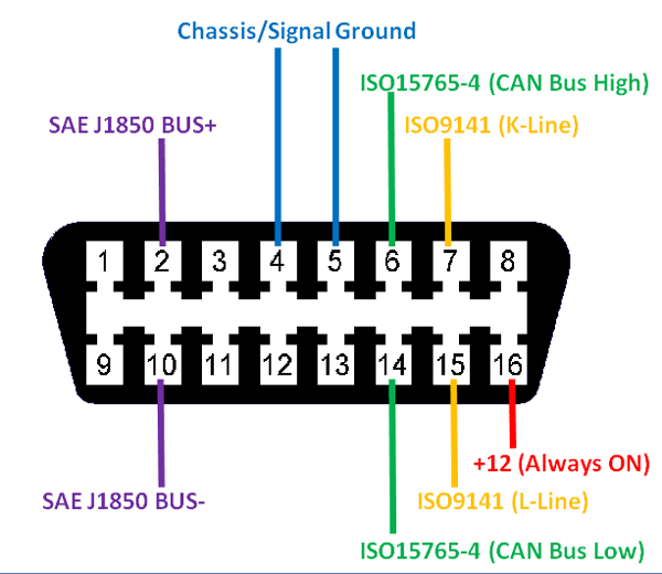
If you plan to also install the satellite radio tuner, it too needs the K-Line, CAN-H and CAN-L signals. These wires can be connected to that module too. A reminder - the CAN-H and CAN-L wires should be twisted together for best signal integrity. Here is a photo of my installation. The CD changer has been replaced with the Phatnoise Phatbox digital media player, and the box below it (with the Audi logo) contains the Bluetooth phone module. 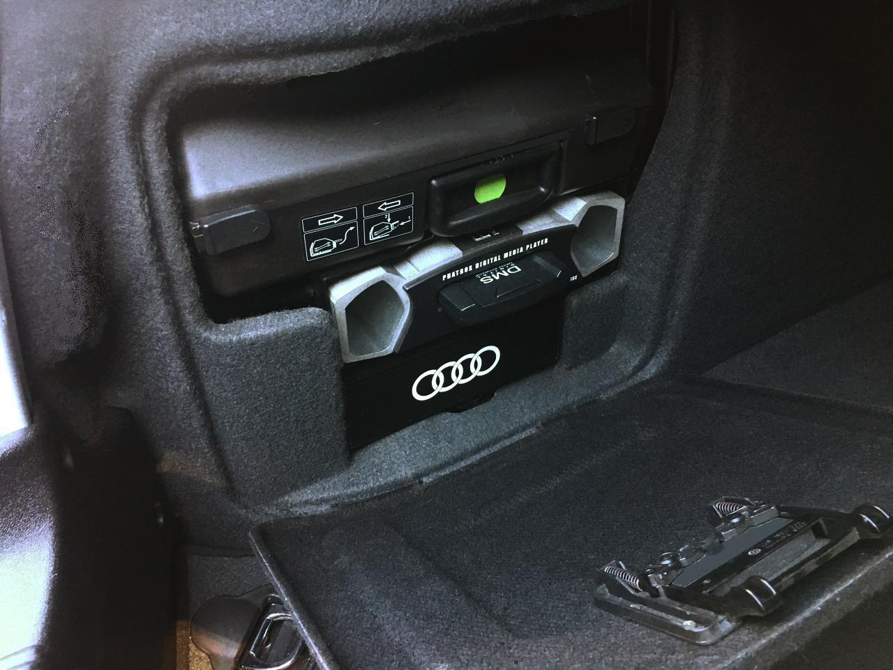
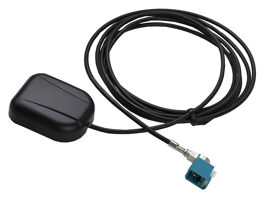
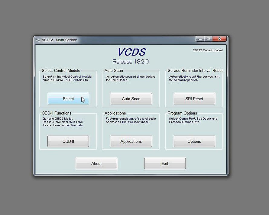
I originally used a 8P0 862 335 L Bluetooth module, it worked, but eventually failed. I swapped in a 8P0 862 335 R, and found that it offered better voice quality, particularly as heard by the other party. Note that these module versions are for North America only. European market use different part number suffixes. See Audi Bluetooth phone module versions (PDF) for a list. If your module did not include an antenna, the part number is 8P0 035 503 E. After installation of the Bluetooth phone module, perform soft coding and adaptation of this module using the instructions found here: Bluetooth telephone coding and adaptation You must also recode the RNS-E to enable Telephone functionality. To do so, see the RNS-E coding and adaptation page. In the Soft coding section, under the 0xxx?xx: Telephone Preparation subheading, set the code to 6. Lastly, the instrument cluster needs to have its adaptation changed to make it show the RNS-E and telephone supplemental information in the DIS. To do so, in VCDS, connect to the 17-Instruments module, then click Adaptation - 10. In the adaptation window, select channel 062. The value should be the sum of the following:
    +1 = Radio
    +2 = Telephone OR Telematics (NAR)
    +4 = Navigation System
    +8 = Telematics (RoW)
The value should be 5 with RNS-E but no telephone module,
or 7 with RNS-E and the North American version of the
Audi Bluetooth Telephone module.
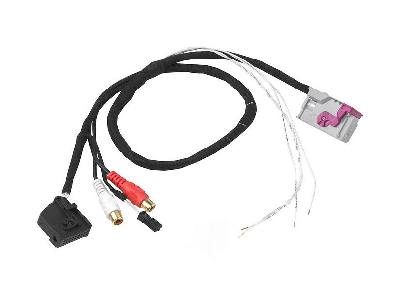
Bluetooth audioIf you would like to stream music from your mobile device to the RNS-E via Bluetooth audio, you can install a small Bluetooth audio module to be plugged into the 32-pin A/V input connector on the back of the RNS-E. One such module is shown in the photo below, and can be found on eBay.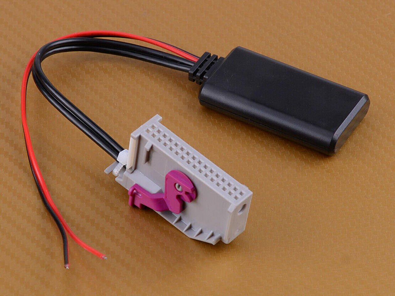
You need to provide 12V power to this module, which can be tapped from the quadlock adapter's pin D13 (U14 St DSP - Radio on). This pin has 12V when the RNS-E is turned on. Ground can be tapped from pin D12 (KL31). In order to use Bluetooth audio, you need to code the RNS-E to enable AUX input. See the RNS-E coding and adaptation page, under the Soft coding section, in the 0xxxx?x: Equipment I sub-section, make sure the "+4 = Analog Input (AUX/PR-UF0/UF1/UF2) installed" is added to your final value. If necessary, change the soft coding. Then, pair your mobile device with the module and then select to use AUX input on your RNS-E to stream music from your mobile device to your car's sound system. Satellite radio tuner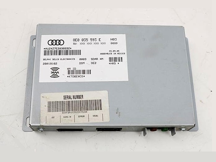
The RNS-E supports an Audi satellite radio tuner module. If you want to install such a module, refer to nsxjr's article (section 2) for full details. I did not install one in my B5 S4. Rear view camera (RVC)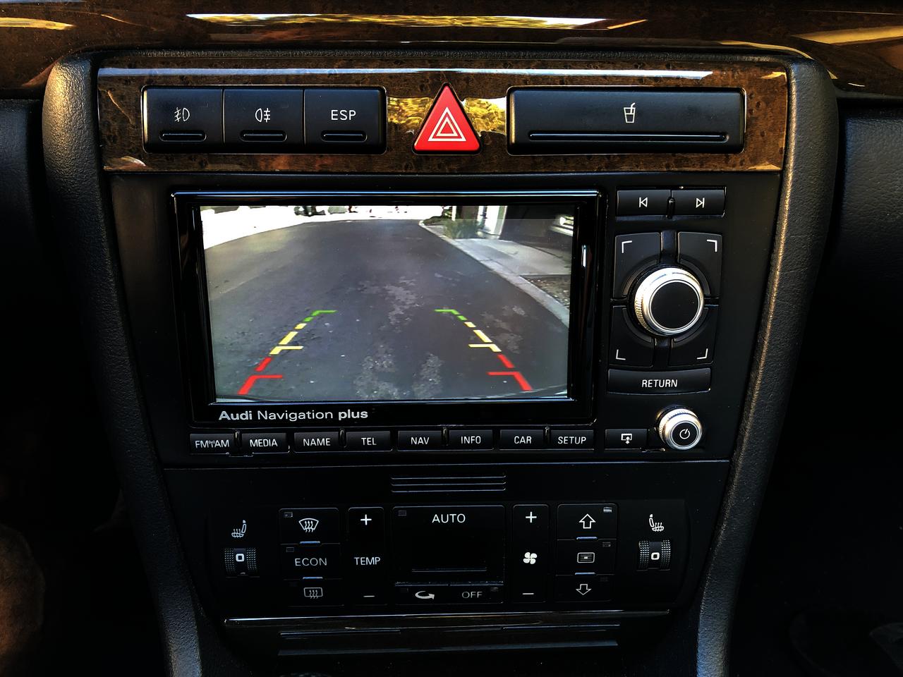
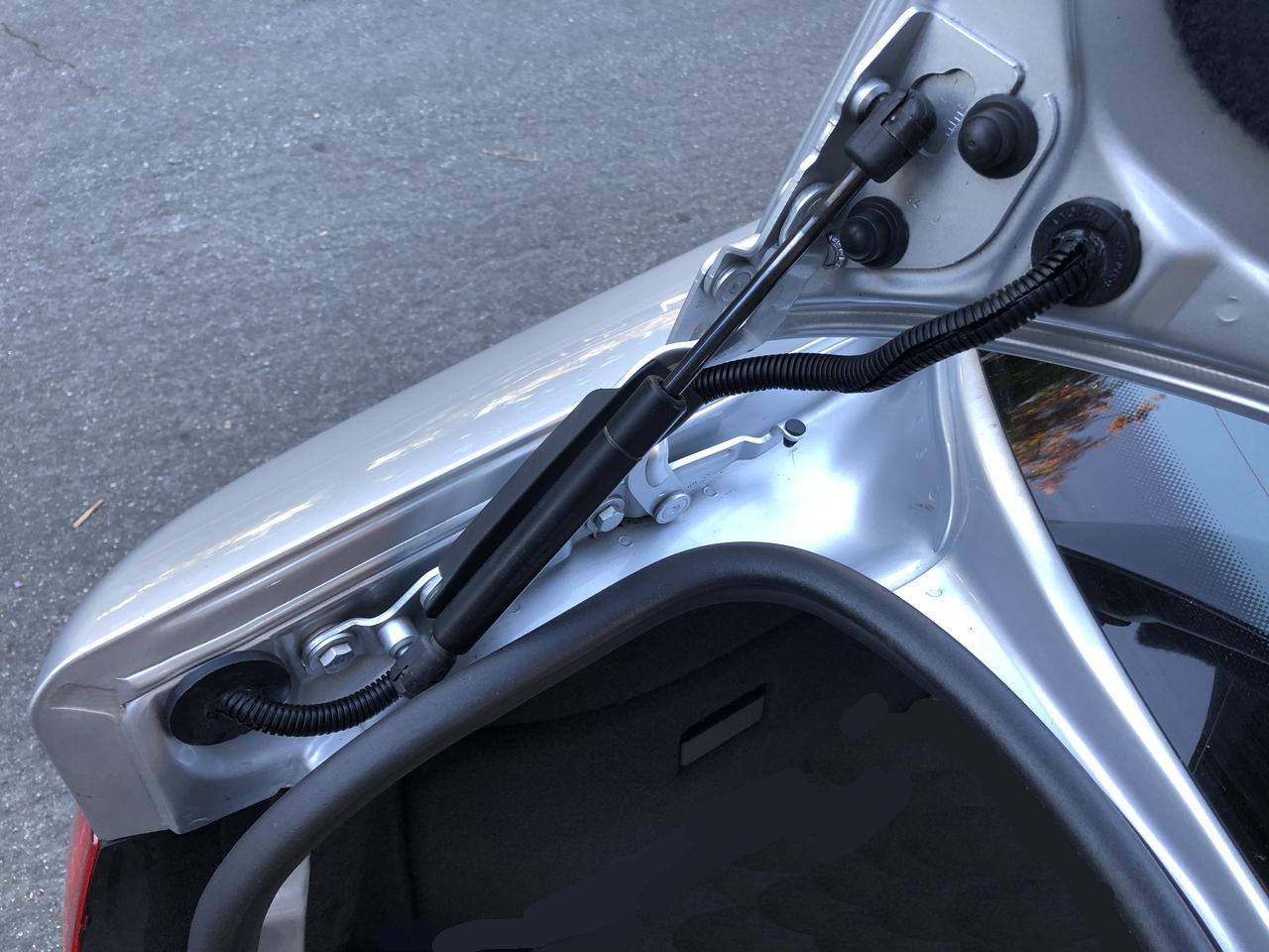
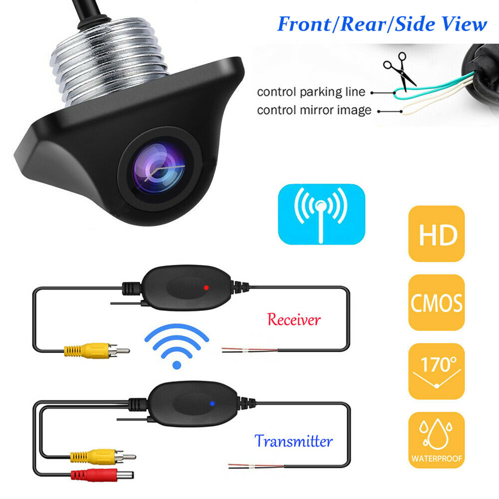
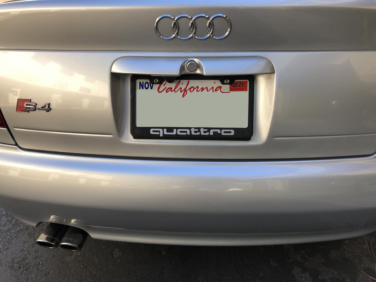
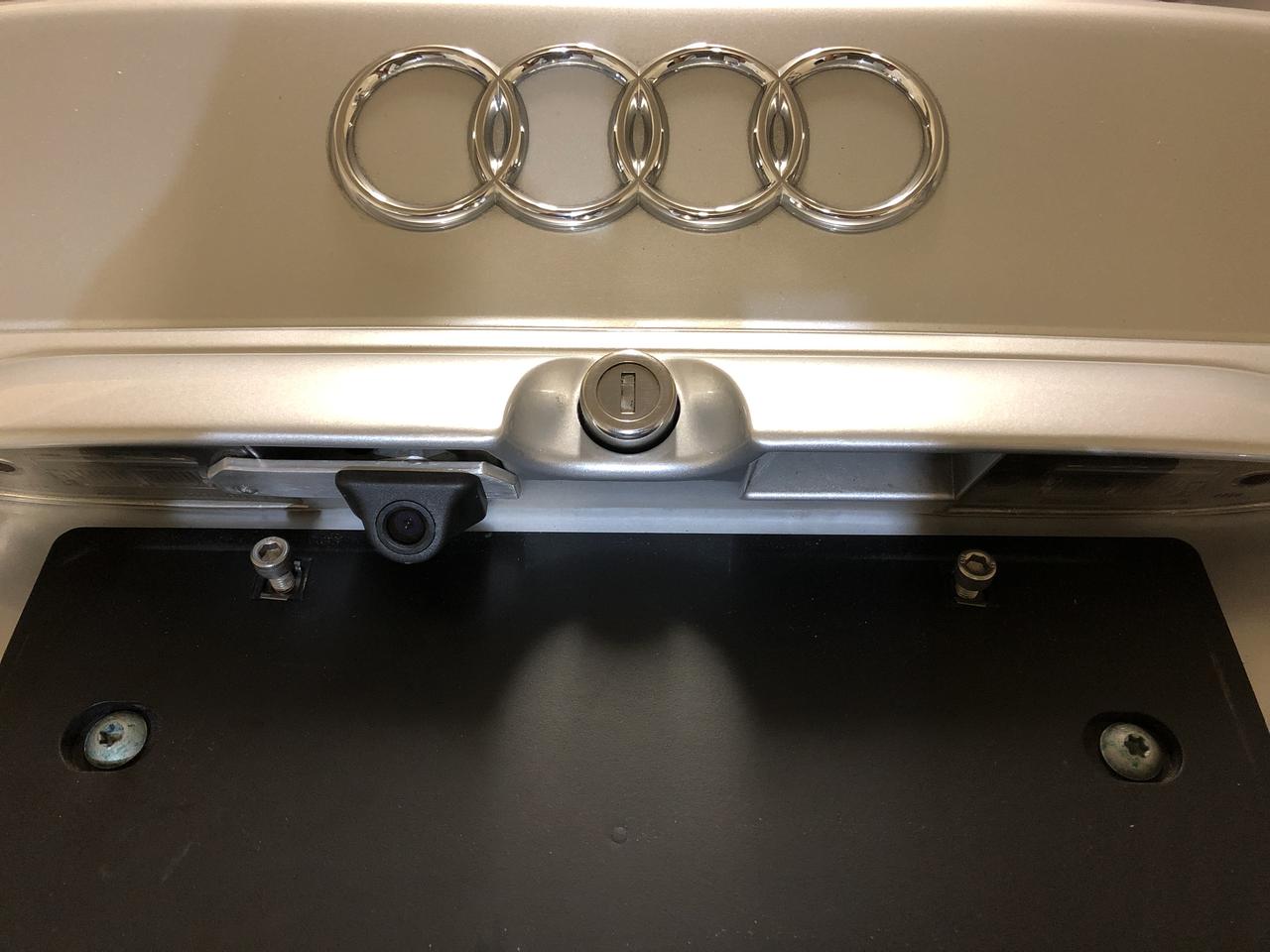
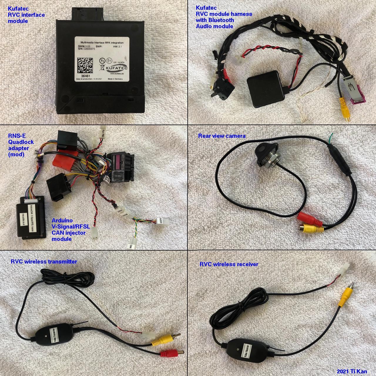
The RNS-E screen can display the rear view when the car is shifted into reverse gear, if a suitable rear view camera is mounted on the trunk lid and a RVC interface module is installed. The interface module converts the camera's composite video format into the RGBS (red/green/blue/sync) 4-line format needed by the RNS-E. In addition, I chose a camera that comes with wireless video transmitter and receiver so that the camera's video signal wire does not need to be run from the trunk lid to the RVC interface module (located in the center console behind the RNS-E). This simplifies the wiring a lot and makes the installation much easier. To enable rear view camera support on the RNS-E, it needs to be running the updated firmware from Stuart M. at RNS-E Firmware Updates. This is because it is necessary to set the adaptation for back-up camera to Lamborghini mode, but the Audi factory firmware does not allow that unless the RNS-E itself is coded for Lamborghini. This doesn't work well on the B5 platform, and the startup splash screen would show the Lamborghini logo instead of Audi. Stuart's updated firmware allows the adaptation to Lamborghini mode while coded for Audi A6, the correct coding for the B5 platform. You need to set an adaptation on the RNS-E to enable the camera. See the RNS-E coding and adaptation page. In the Adaptation section, under Channel 004: Back-up camera, make sure to set the value to 1 (Back-Up Camera installed - Lamborghini). With this setting, the RNS-E will switch to camera view when in reverse gear.
I used the following components for the RVC functionality:
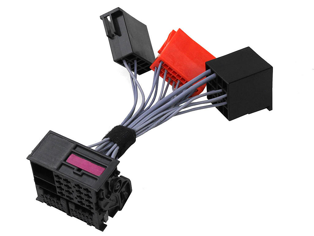
Tapping into the quadlock adapterIn several instances (as mentioned above) it is necessary to modify the quadlock adapter by tapping into its wires. 3M Scotchlock connectors are commonly used for this purpose, but they are bulky and may not be reliable. If only Scotchlocks are used, then they make quadlock adapter permanently tethered to the devices that the spliced wires go to, making it difficult to remove from the car for service. Rather than doing it that way, I recommend splicing the wires the "old fashioned way" with solder, and to use connectors that can be unplugged. A good choice for this is the Molex .062 series pin and socket connector, which comes in different number of circuits. For the purpose of this retrofit, the 1-circuit, 2-circuit and 4-circuit versions are most useful. Each connector has a male and female plug body, and make and female crimp pins. Each of these are sold separately.The following diagram illustrates the way I recommend these splices and connectors be done. The wire in the quadlock to be spliced into is cut and stripped, the extra wire is also stripped then twisted together with the original wire ends and soldered. The whole joint is then wrapped with heat-shrink tubing for insulation. 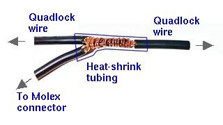
The following photos shows my modified quadlock adapter. You can clearly see the Molex connectors on them. Also shown is the RFSL/V-Signal injector module (for late production RNS-E mk2, see above). 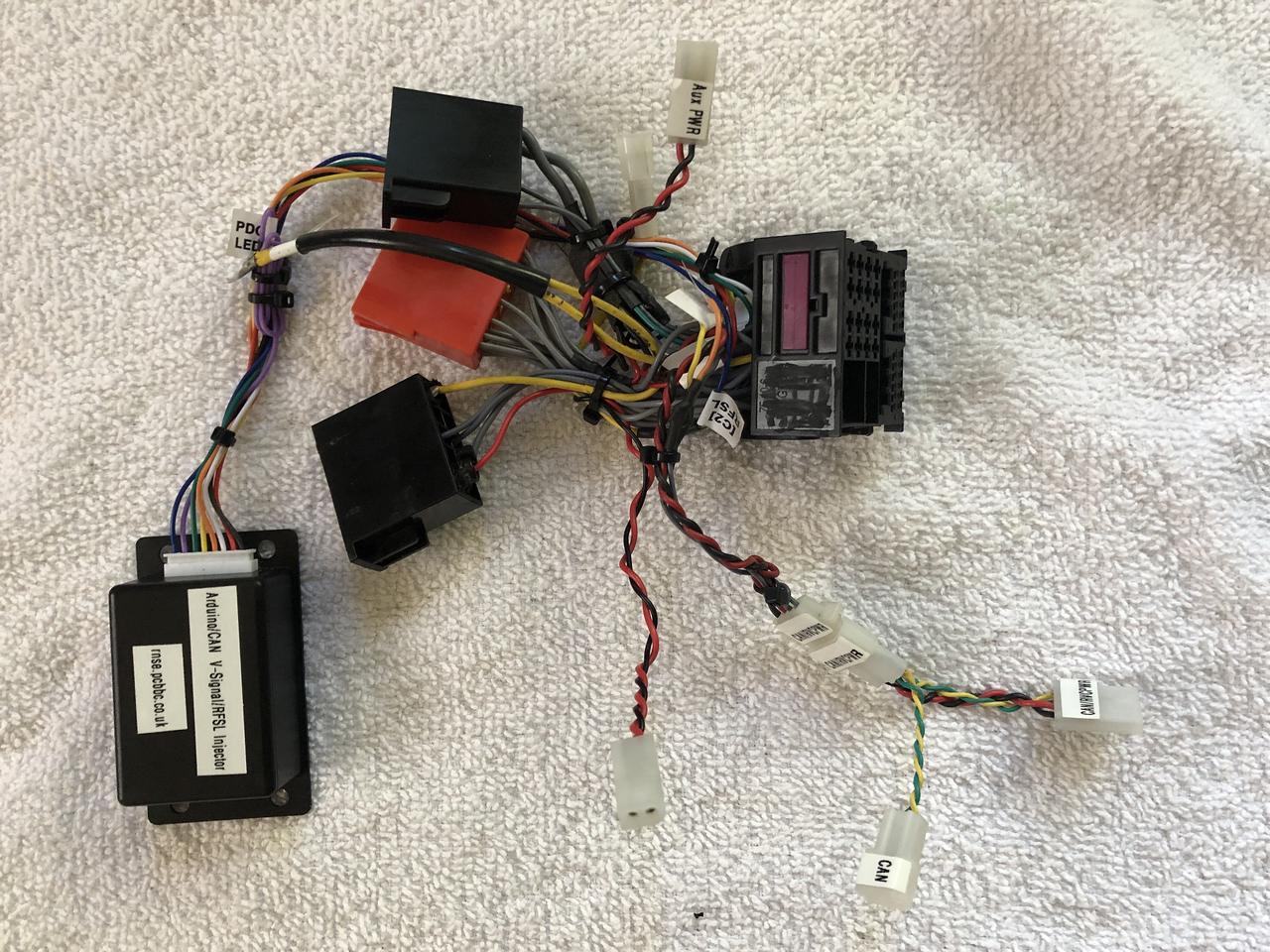
Note that all connectors are labeled to prevent mix-ups. The following are links to Mouser, Digi-Key and Newark where you can purchase the Molex .062 connector housings and pins.
The crimp terminal pins should be used in the plug housing, whereas the crimp terminal sockets should be used in the plug receptacle. The 1-circuit connectors are useful for adding the RFSL wire, the 2-circuit are good for power/ground wire pairs (e.g., the Bluetooth audio module and the RVC video transmitter/receiver), whereas the 4-circuit can be used for power, ground, CAN-H and CAN-L lines (e.g., for the Kufatec RVC interface module). Done this way, the quadlock connector and all other modules can be easily unplugged and removed from the car if necessary. Wiring diagramThe wiring diagram of my B5 S4's RNS-E and related systems is available for your reference. It includes the RNS-E, Phatnoise Phatbox, Bose amplifier, speakers, Bluetooth audio module, Bluetooth phone module, rear view camera system and more. You can compare the descriptions in this document with the wiring diagram to help understand how it's all connected.Stuart M. RNS-E firmware updatesAs mentioned previously, there are several instances where a firmware update to the version from Stuart M. at RNS-E Firmware Updates is necessary, there are circumstances where the stock Audi firmware may work adequately well (the clock sync issue notwithstanding). Nevertheless, Stuart's firmware adds a number of useful and fun features that I recommend it for all RNS-E users. See his website for full details.Links
|
||||||||||||||||||||||||||||||||||||||||||||||||||||||||||||||||||||||||||||||||||||||||||||||||||||||